Note: These pages refer to the gonio-photometer built by me around 1990 at Fraunhofer ISE, Freiburg. For the newer post-2004 gonio-photometer PG2, developed by me at my pab Ltd, please check the pab Ltd website.
My diploma thesis 1989-1990 in Physics consisted of designing, building and operating an out-of-plane gonio-photometer
for BSDF measurements at Fraunhofer ISE from scratch.
This included shaping and fitting models for the Radiance simulation program,
used in day-lighting.
Many of sample of new window materials, mostly translucent insulation types, have been measured with it over the years and for multiple
European research projects.
NB: The term BRTF (bidirectional-reflection-transmission-function) was used throughout the diploma work, with a definition
identical to the BSDF (bidirectional-scatter-distribution-function), conclusively: BRTF=BSDF .
| | | | | | |
|
An English translation was completed in March 2021, and filed at ArchivX.org:
http://arxiv.org/abs/2105.15112 , "Design and Construction of a Device for Measuring
Light-Scattering on Anisotropic Materials" by Peter Apian-Bennewitz.
A scanned PDF of the original printed version in German, an 8MB PDF file with image resolution 800x1200 pixels, is available
here.
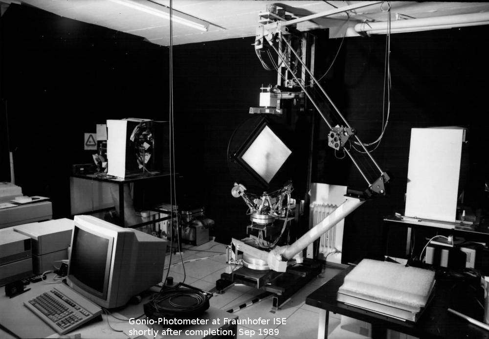
After checking existing concepts and some thoughts on my own, the initial design featured two parabolic mirrors (light house mirrors)
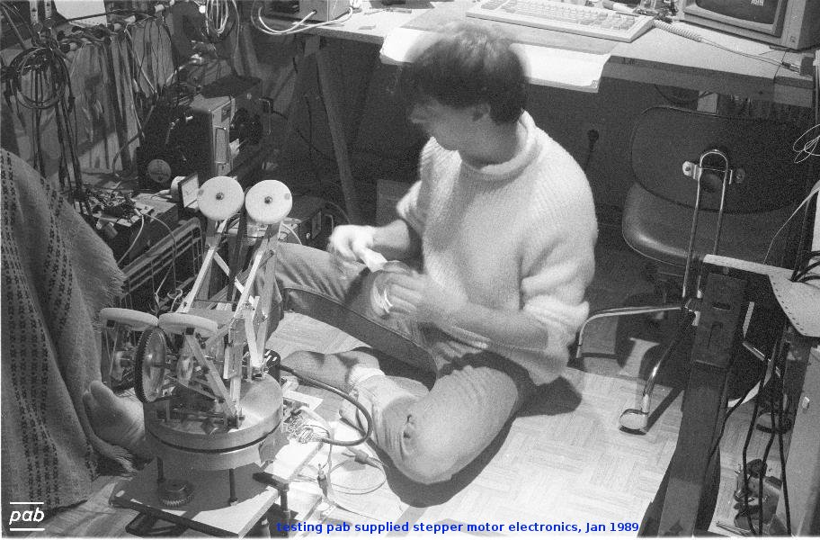
with halogen lamps, full 4 axis control using high-end 5-phase stepper motors and a detector rail system that covered
a quarter of a sphere.
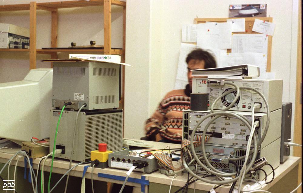
This setup is shown below, all images taken by me at FhG-ISE, except first photo showing the sample mount and stepper motors under test,
which was done at my place.
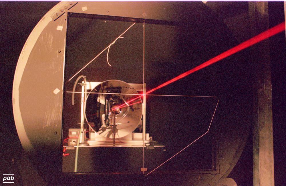
Part of the first parabolic mirror is visible on the left side, around is a card-box with black surface to shield stray light. The
second mirror is on the right hand side. The laser beam in the image is generated by a HeNe Laser mounted at the wall behind the first mirror
and served as the primary reference for alignment.
The detector is mounted on the carriage on the linear rails and was aimed towards the source by adjusting a gear drive by stepper motor.
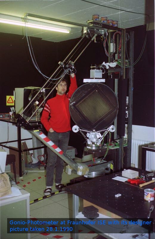
Barely visible is the drive system for the vertical axis. My basic arrangement of bearing, motor and timing belt proofed sound over the
years. 20 years later the idea was reused in a more elaborate and compact version with
my PG2 gonio-photometer.
In retrospect, the main drawback of the first design had been the use of the steel ''backbone'' (towards the wall) that limited a 360deg
movement, and the inflationary use of adjustment screws. It was a little laborious to align, compared with my later gonio-photometer PG2.
The linear rail was replaced by a half-circle rail during my PhD work, see link ''Part 2'' above.
 |  |  |  |
 |  |  |  |
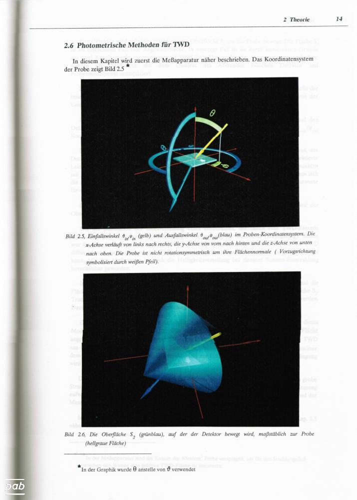
Together with the two axis sample holder, the design ensured that every incident and outgoing angle could be measured, while using a
commercial (COTS) linear rail system for the second detector axis. The latter is a nice, economic and reliable way to move the detector
precisely, but from a physics point of view, the varying detector distance introduces errors that are hard to compensate for.
All axis had full computer control, using 5-phase stepper motors.
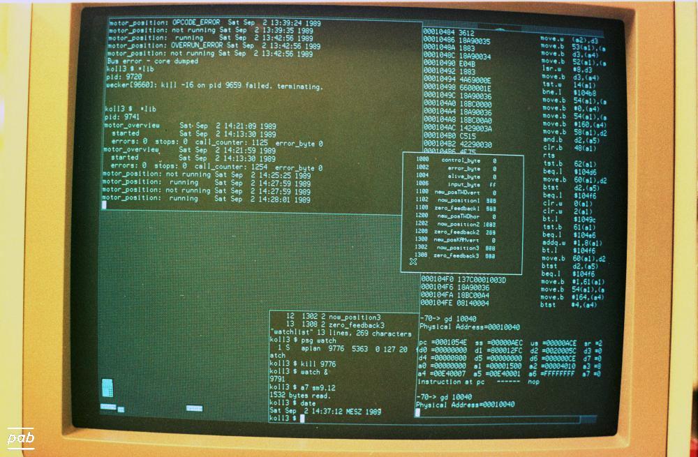
Motor control was by my own assembler program running on "SAC700" VME boards by Eltec. These featured an MC68000 CPU, so the HP-UX assembler on the
HP360 workstation (running an MC68030 CPU) could be used. Program download, parameter setting and monitoring was all done through the
VME-bus expander (HP model 98577A is shown in the image) of the HP360.
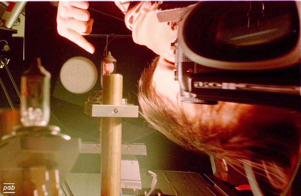
The initial light-source were 2 Halogen lamps, actually H4 headlights, mounted on a post at the focal point of a parabolic mirrors (see image
above).
A later refinement was a frame with a set of tensioned and adjustable steel-wires to position the H4 lamp, minimising the shadow caused by the
lamp mount.
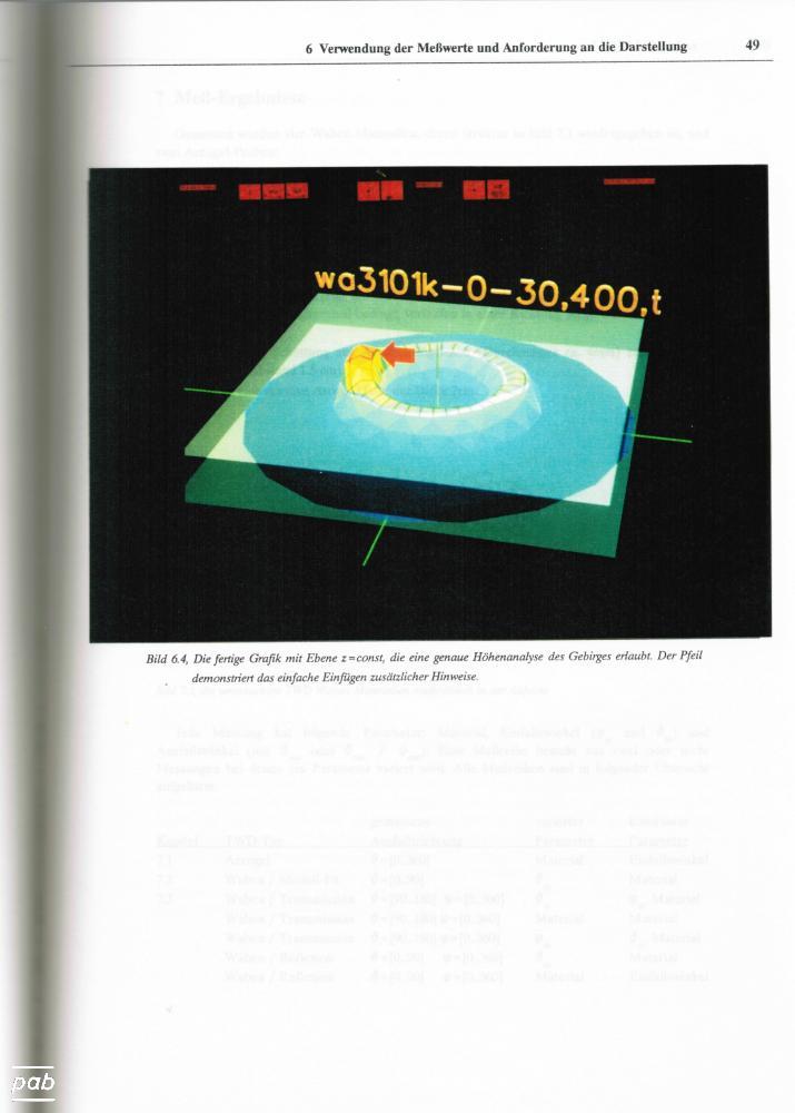
The data processing saw a first version of my program mountain, based on the ray-tracing software "Rayshade" to do the visualisations.
Note the honeycomb samples in the wide angle photo, on the table on the right.
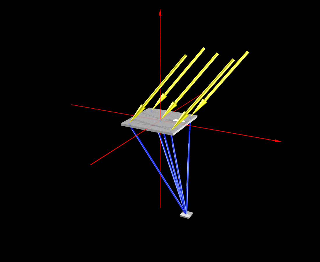
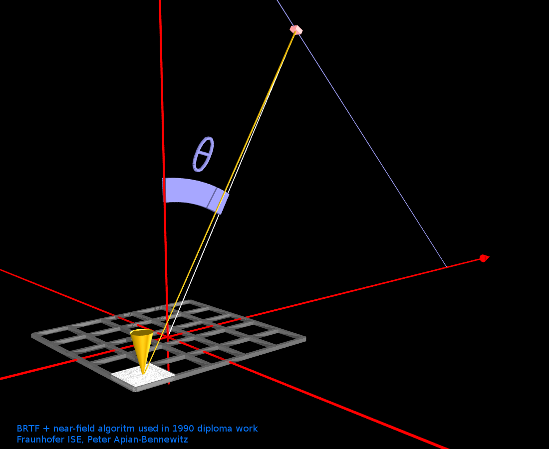
The large illuminated area of the sample causes converging beams from sample to detector with different outgoing angles (see original images from 1990 below).
| far-field detector at infinity | near-field detector at finite distance |
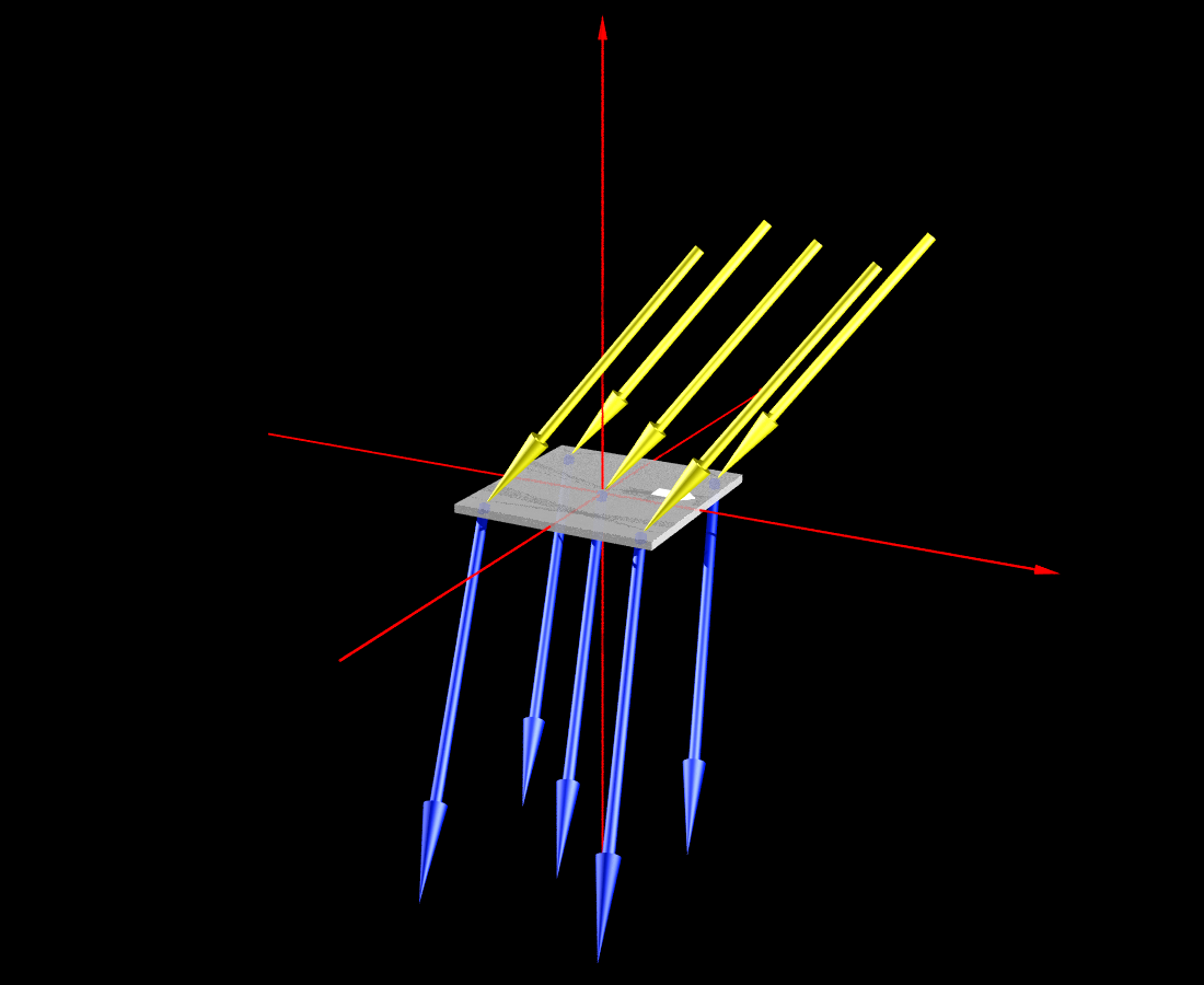 | 
|
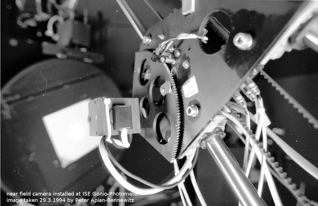
To handle this, a CCD camera (compact head and separate electronics) for near-field photometry had been added to the gonio-photometer already in 1990. In image below, the camera head and optics are mounted on the left side of the gear disc, with the camera electronics in an extra housing. The image of the desk shows the monitor on top of a power supply. Later a frame-grabber card was installed in the VME bus to get a digital image. However, the overall dynamic range, with video and frame-grabber, turned out to be considerably lower (1:40) than the data-sheet of the Thompson CCD chip had specified (1:5000).
 |
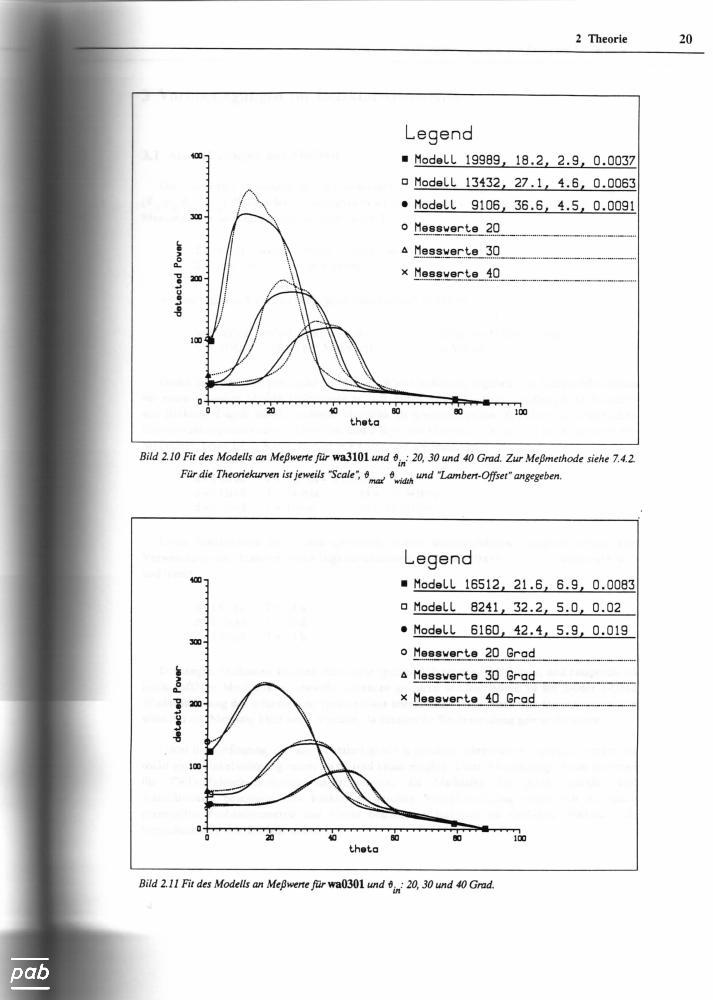
To handle this, a numerical model for the BSDF and the near field situation was implemented and its parameters fitted. The
Levenberg-Marquardt fit included summing up the distributions from the patches. Results had been quite reasonably, taken that the model for
the cone shaped BSDF had been relatively simple.
Results below include the original 1989 plots (HP-GL generated by the plot program "Disspla"), de-dusted, annotated and converted to SVG
format in 2011 for web use.
 |  |  |
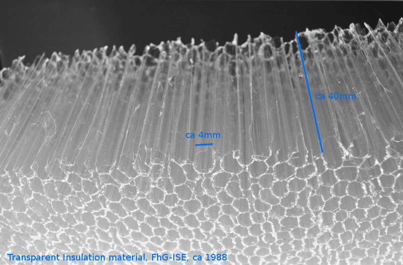
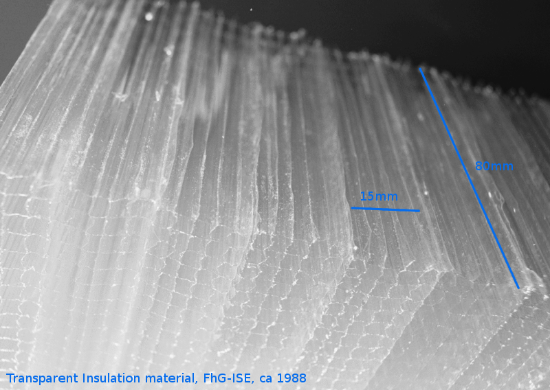
Activities revolved around "transparent insulation" material, a topic which was very much "en-vogue" at Fraunhofer ISE in the nineties.
The central idea is to have a high radiation energy flux from the outside to the inside, while keeping thermal convection and conductance in
to the outside to a minimum.
Different production methods and materials had been tested in European research projects.
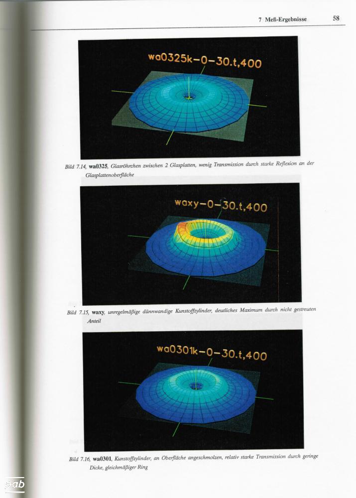
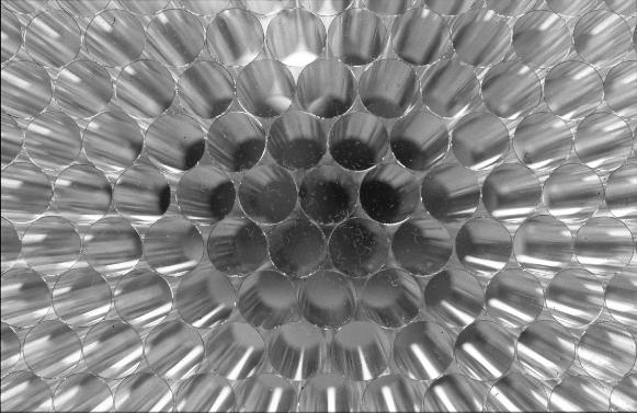
The last image in the following list shows an example of fairly advanced glass tubes with very thin walls and approx 6mm diameter.
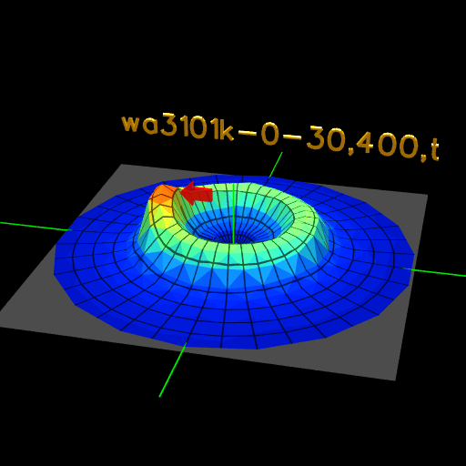
All tube-based TI material shows a cone-shaped BSDF, which may cause glare of the material is used in bright sunlight and within view.
The width and shape of the scattering depends on material and production method.
| "straw" like material wa?? | laminated strips wa3101 | glass tubes wa0325k |
 |  | 
|
| legacy data not yet available | 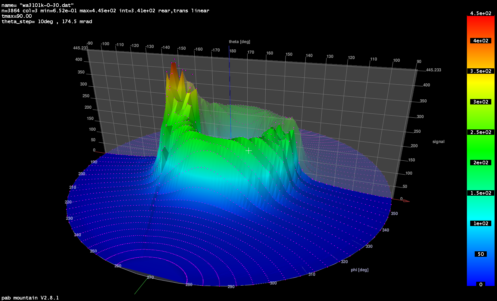 | legacy data not yet available |
The historic data example for sample wa3101 shows one of the early BSDF (incident angle 30deg), measured on Saturday January 6 1990, 17:33.
This screen dump used a newer version of mountain, which shows a lot more detail then the Rayshade
generated visualisation in the diploma work (see image in scanned version above). By today's standards, the angular resolution of
this particular peak had been too low.
An algorithm for automatically refined angular scans had been added later.
Since BSDF of this kind of material is non-standard and complex, it provided a very nice introduction to the art of BSDF measurements.
next: further work work based on this gonio-photometer (PhD, etc)